|
Unwind guiding with tension control (pay
off reel system)
Unwind with edge / line guiding and tension control
Controlled unwind guiding
Description:
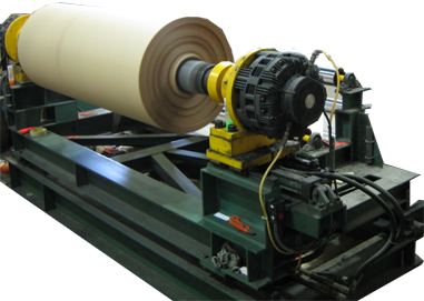
 Standard adapter bases consist of a stationary floor-mounted
frame or plate, a four unit, standard bearing and support
system, and a moving frame or plate. A heavy duty servo
cylinder is mounted between the frames and the bearings. The
servo cylinder moves the upper adapter base plate back and
forth in response to hydraulic signals from the power unit. The CON-PAP-TEX adapter base is designed for use in applications where the unwind or rewind stand must be shiftable. Standard adapter bases consist of a stationary floor-mounted
frame or plate, a four unit, standard bearing and support
system, and a moving frame or plate. A heavy duty servo
cylinder is mounted between the frames and the bearings. The
servo cylinder moves the upper adapter base plate back and
forth in response to hydraulic signals from the power unit. The CON-PAP-TEX adapter base is designed for use in applications where the unwind or rewind stand must be shiftable.
Standard adapter base assembly consists of stationery mounted
frame, which adopts the existing unwind / rewind stand with
shaft and breaks. In the unwind guide, the idler rollers are
attached to moving frame before fixed detectors to stabilize
web & idle for slitter machines. In the winder guide, the
sensor is attached to the moving frame after fixed idler
rollers, with sufficient wrap to get perfect winding of
material. We can make special kind of rewinding structure
where motors also move along with rewinding rolls.
Applications:
The CON-PAP-TEX adapter base is designed for use in
applications where the unwind or rewind stand must be shift
able. By fitting the adapter base under the stand, a simple
and economical installation is obtained. Because of the
relatively high mass of the unwind or rewind rolls, its use
is most often found in applications. Where response time can
be relatively slow and where accuracies are not overly
critical.
In
Rewind guide the detector is attached to the moving frame
before fixed idler with sufficient warp to stabilize Web.
In
Unwind guide the idler roller attached on moving frame before
the fixed detector to stabilize the Web.
Unwinding:
If
the material wound is irregular, this system guide the edge
position and let it regularly into the subsequent process.
The idler roll moves with the unwinding reel stand.
v
Mount the
detector fixed and as close to the idler roll as possible.
v
The leaving
web formed a angle at the deflector roll should more than
30-. if not possible, apply a pinhole added. The important,
do not allow the web slip on this roll. The distance between
two rolls should be more than the maximum width of the web.
|
